Build a cheap, flexible AVR microcontroller programming target board
 Programming AVR microcontrollers using ISP is a simple process when the target is on a board exposing a 6 or 10-pin ISP header. But what if you have different types of AVR chips? Their SPI pins (VCC, GND, MOSI, MISO, SCK) aren’t always in the same locations.
Instead of buying different types of target boards or buying an expensive generic programmer, I built one using a small breadboard, a Universal 28 pin ZIF DIP socket and 6 male-male hookup wires that I connected to my USBtinyISP programmer.
The following steps detail the assembly process:
- Align the first row of pins on the ZIF socket with the first row of pins on the breadboard: this will make it easier to match the SPI pins on the microcontroller with the ISP connector pins later
- Make sure that you have room for hookup wires on both sides of the ZIF socket
- Insert the ZIF socket into the breadboard
- Ensure that your ISP programmer is disconnected from your computer
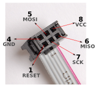
- Insert one end of the hookup wires into the 6-pin cable connector like this:
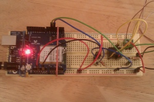
- Using the datasheet for the AVR chip you want to program, find the pin numbers of the VCC, GND, MOSI, MISO and SCK pins. For example, the ATtiny85 shown in the picture above has the following pin out:
- Insert the other end of the hookup wires into the breadboard according to chip’s pin out.
- Connect your AVR programmer to your computer.
- Using avrdude, type the following command: C:\avrdude -c usbtiny -p t85.
- You should get this output if everything was connected properly:
 avrdude: AVR device initialized and ready to accept instructions

Reading | ################################################## | 100% 0.01s

avrdude: Device signature = 0x1e930b

avrdude: safemode: Fuses OK

avrdude done. Thank you.
I’ve successfully tested this target board with an ATtiny85, ATtiny84 and an ATmega368 / ATmega168:
C:\avrdude -c usbtiny -p t84

avrdude: AVR device initialized and ready to accept instructions

Reading | ################################################## | 100% 0.01s

avrdude: Device signature = 0x1e930c

avrdude: safemode: Fuses OK

avrdude done.  Thank you.
C:\avrdude -c usbtiny -p m328p

avrdude: AVR device initialized and ready to accept instructions

Reading | ################################################## | 100% 0.16s

avrdude: Device signature = 0x1e950f

avrdude: safemode: Fuses OK

avrdude done.  Thank you.
So, what happens if the ISP connector is connected to the wrong pins on the microcontroller?
Not much really: the USB bus on your computer may shut itself down, requiring a computer reboot or avrdude will fail to communicate with the chip. In either case, make sure that the ISP programmer is always disconnected from your computer before switching chip types or changing the position of the hookup wires in the breadboard and triple-check your hook-up wire connections against the datasheet of the target chip!
Happy hacking!


